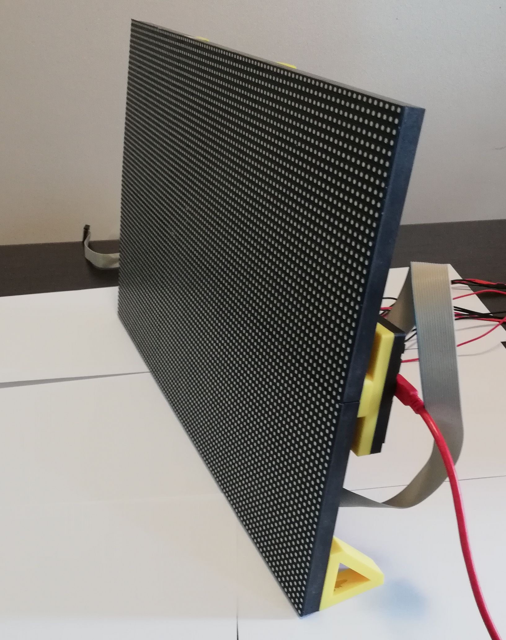
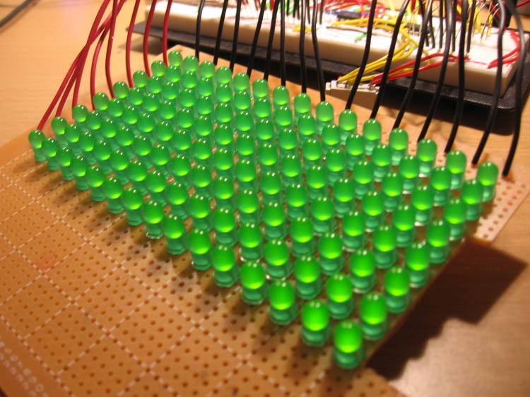
LED Matrix Display Circuit Diagram Figure 5: Arduino Uno 5x7 LED matrix display driver circuit The matrix display used in the example circuit is a CCAR display. It comes in a 14 pin package (figure 6). The pins are aligned in two rows. One at the top and the other at the bottom of the package. Pin 1 is the first pin on the left of the bottom row. Figure 6: LED matrix display

Upload the program to the Arduino and power up the circuit. The LED matrix display should show a colorful rainbow pattern cycling through the LEDs. Adjust the code and experiment with different patterns and colors. Conclusion. Building a colorful LED matrix display with WS2812B modules allows for creating dynamic lighting effects and visual This circuit connects an ESP8266 NodeMCU microcontroller to an 8x8 LED matrix display. The NodeMCU controls the matrix using digital pins D5, D7, and D8 for chip select (CS), data input (DIN), and clock (CLK) signals, respectively. The circuit is designed to display patterns or characters on the LED matrix, which are driven by the microcontroller.

PDF System Design Guidelines for Full Circuit Diagram
This circuit features an Arduino UNO microcontroller connected to multiple 8x8 LED matrix displays and pushbuttons. The pushbuttons are interfaced with digital pins D2, D3, and D4 on the Arduino for input, while the LED matrices are connected to digital pins D5 through D10 for control signals.

MAX7219 Module Overview. The MAX7219 module is a popular choice for controlling LED matrix displays, and it comes in different variations. Among them, two widely used types are the generic MAX7219 module and the FC-16 module.While both serve the same fundamental purpose, there are slight differences in their design and pin configuration, making it essential to choose the right module based on

Arduino Tutorial - Arduino Getting Started Circuit Diagram
The circuit diagram of the 7×5 LED matrix display using Arduino is shown in figure 1. The entire circuit of LED matrix is built around Arduino uno board, few NPN bipolar junction transistors (7 nos. in 7×5 display), a few numbers of resistors (equal to the number of transistor i.e. 7), and LEDs (7×5 = 35 nos.).
